PCB mounting?
-
jacob
- Site Admin
- Posts: 16077
- Joined: Fri Jun 28, 2013 8:38 pm
- Location: USA, Zone 5b, Koppen Dfa, Elev. 620ft, Walkscore 77
- Contact:
PCB mounting?
I'm making a solar powered USB charger out of a 12V panel and a so-called "buck converter". I'm not sure how to mount it securely since the PCB has no screw holes. The internet suggests using hot glue or even double-sided velcro tape, but that seems kinda ghetto to me?! In particular, inserting the cable into the USB jack requires quite a bit of force. Since stringing together a bunch of small prefab circuit boards seems rather common for various projects these days, it would be nice to have a neater mounting solution than a hot glued rat's nest.
-
ducknald_don
- Posts: 333
- Joined: Thu Dec 17, 2020 12:31 pm
- Location: Oxford, UK
Re: PCB mounting?
If you have access to a maker space or a friend with a 3d printer then a custom enclosure or snap-fit solution could be a way. Given your creativity with the flight controller they could probably be made with something you have at hand instead.

Re: PCB mounting?
First off; from this perspective now I probably would have bought a buck converter with mounting capabilities. There seem to be plenty around that can be mounted nicely and easily for very slightly more money. But I probably would have done the same thing initially without thinking about it, and ended up in the same situation.
When I built stuff with little PCB boards I used to have access to a whole machine shop where I could rig something up out of acrylic / etc to build nice mounts for stuff. These days, it looks like everyone and their mom is 3d printing those (as rref points out above). Without access to that, I would try and find or build some plastic bits that can hold it in place (plastic soldering or maybe plastic molding style, and be sure to do this outdoors and wear a mask). Some plastic clips for something else that would hold onto the PCB and could be mounted to a stand might also be viable... maybe some leftover / old hair clips would work for mounting this and then could be attached to a mounting board?
Another option might be to disassemble some existing plastic junk and salvage the plastic parts that connect two parts together with screws (I'm mostly thinking junked kids toys here), then use 3 of those and the screws to sandwich the PCB so it is touching the plastic parts but not the screws.
Re: PCB mounting?
Those look like they are made to be soldered to posts which are both the mounting and power supply points.
You could solder the PCB to wire and then cover the bare metal with heat shrink tubing, or nothing at all. It might get hot under load so heat shrink might be a bad idea.
If you need to mount it on something, double sided tape would work, but pushing the USB connector in and out could break the bond eventually.

Re: PCB mounting?
Maybe just a small dab of jb weld steel stick or plain old epoxy

Re: PCB mounting?
Your wood working tools should be sufficient for fabricating a nice set of rails to mount the board. If the engineer laid out enough margin on the edges of the PCB you can make some slot rails out of insulating materials of choice and affix them to your enclosure or whatever you want to mount to.
Just need to dig out a blade with the right kerf. You can make some wooden rails that function like this. Just in wood instead of aluminum extrusion. Wood is better because it won’t short your board.

Or this but in wood.

ETA - I found these commercial ones. These can be replicated in wood with a table saw and drill.
https://www.mouser.com/datasheet/2/123/ ... 265562.pdf
I must say a $99 3D printer is great to have around for this kind of thing. There’s really no excuse now. If you have the room it’s worth it to make all kinds of little things. Saves trips to the store or Amazon Prime. Move electrons don’t move stuff. My machine has paid for itself many times over because I have sold dozens of copies of a single machine part for $20 profit. It’s stupid easy to have a “free” printer.
Here is how I make a PCB mount + enclosure all in one.


Or this,

Or this

Just need to dig out a blade with the right kerf. You can make some wooden rails that function like this. Just in wood instead of aluminum extrusion. Wood is better because it won’t short your board.
Or this but in wood.
ETA - I found these commercial ones. These can be replicated in wood with a table saw and drill.
https://www.mouser.com/datasheet/2/123/ ... 265562.pdf
I must say a $99 3D printer is great to have around for this kind of thing. There’s really no excuse now. If you have the room it’s worth it to make all kinds of little things. Saves trips to the store or Amazon Prime. Move electrons don’t move stuff. My machine has paid for itself many times over because I have sold dozens of copies of a single machine part for $20 profit. It’s stupid easy to have a “free” printer.
Here is how I make a PCB mount + enclosure all in one.
Or this,
Or this
-
jacob
- Site Admin
- Posts: 16077
- Joined: Fri Jun 28, 2013 8:38 pm
- Location: USA, Zone 5b, Koppen Dfa, Elev. 620ft, Walkscore 77
- Contact:
Re: PCB mounting?
Uhm... no, not quite. The mm-scale tolerances are too small, so I just built a small box and jammed two buck converters in there. An exercise in building tiny doll houses or filing cabinets
Which of course they didn't, not even the slightest. Would have been nice though.
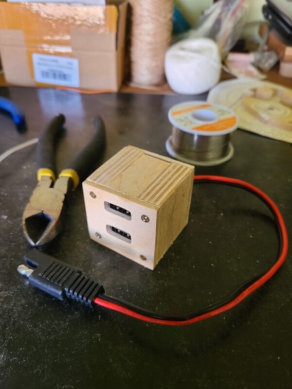
PS: Those SAE connectors are for lack of a better word "fucked up". Maybe it makes more sense in some alternate universe I've yet to visit. The only way I can make sense of the idea behind it is that whether the "naked" metal part is sink or source, it must always be ground. This overrides the red/black coloring of the wiring. Maybe I'm just abusing the wiring for something that it was never intended for anyway. My PV panel came with a connector, so I can plug my "cube" into the cigarette lighter (or the panel) and maintain the correct polarity.
Re: PCB mounting?
I understand that your problem has been solved. That being said, I'd like to share a simple, fast and mostly free ghetto way of fastening pcb's: plastic bottle caps.
- Cut a groove into the side of the bottle cap.
- Turn it upside down.
- Screw the flat side to a piece of wood.
- Repeat.
- Lock the pcb into the groove.
Don't ask me how I know...
- Cut a groove into the side of the bottle cap.
- Turn it upside down.
- Screw the flat side to a piece of wood.
- Repeat.
- Lock the pcb into the groove.
Don't ask me how I know...
Re: PCB mounting?
I like that one. Good upcycling.
Yeah for exposed pins on plugs make sure they are on the cold side. If you’re finding your +be terminal as bare metal make sure it’s the side downstream of the battery so that when it drags on the grounded chassis it doesn’t spark. Those are not my favorite plugs.
Yeah for exposed pins on plugs make sure they are on the cold side. If you’re finding your +be terminal as bare metal make sure it’s the side downstream of the battery so that when it drags on the grounded chassis it doesn’t spark. Those are not my favorite plugs.
Re: PCB mounting?
I had an electric bike with those plugs. One morning I disconnected the battery from the charger and plugged it to the bike (I thought), but by mistake plugged it to another battery pack. A big arc flashed and the plug ends vaporized. My hands were badly burned and were covered in black rubber that did not come off for weeks. I don't use that style of connector anymore.
-
jacob
- Site Admin
- Posts: 16077
- Joined: Fri Jun 28, 2013 8:38 pm
- Location: USA, Zone 5b, Koppen Dfa, Elev. 620ft, Walkscore 77
- Contact:
Re: PCB mounting?
Yikes!
It's logically possible to make the connections self-consistent. If the connector comes from a source (battery, cigarette lighter, PV panel), then the bare end has to be grounded. If it's connected to a sink (like above), then the bare end has to be hot. I don't know if this is "official specs" though.
What's confusing is really the red/black wire scheme. (This may be my fault from stealing that connector from elsewhere although in this case it turns out right.) As it is, I'm not trusting any connections w/o checking with a multimeter.
Re: PCB mounting?
That does not help when you inadvertently connect two sources. Anderson Powerpole connectors solve this problem.
-
jacob
- Site Admin
- Posts: 16077
- Joined: Fri Jun 28, 2013 8:38 pm
- Location: USA, Zone 5b, Koppen Dfa, Elev. 620ft, Walkscore 77
- Contact:
Re: PCB mounting?
Ahh, yes, I see the problem now.
Re: PCB mounting?
You need fuses in your designs. They’re an afterthought but they’ll save a fire or burning your hands. I’ve seen yellow hot wires evaporate insulation in simple automotive circuits that were not fused…often in university research labs wired up by careless grad students. The one burned into my memory is my classmate trying to grab the glowing wire and pull it out of the circuit with his bare hand in a state of panic. 
Poly resettable or in-line blade fuses (ATC) are your friend.
I like these. Add them in the obvious places in your circuit.

Poly resettable or in-line blade fuses (ATC) are your friend.
I like these. Add them in the obvious places in your circuit.
Re: PCB mounting?
Barrel connectors also work, if you always connect the female side to the source, and the male side to the powered device.