DIY Single axis USB controller

Fixing and making things, what tools to get and what skills to learn, ...
User avatar
Sclass
Posts: 2809
Joined: Tue Jul 10, 2012 5:15 pm
Location: Orange County, CA

Re: DIY Single axis USB controller

Post by Sclass »

jacob wrote:
Tue Oct 24, 2023 2:05 pm

I spent around 10 minutes trying and retrying soldering the pins on. GND was the worst!, what an exercise in frustration! As a good^H^H^H^Hbad workman, I blame my tools.

And wire the power in parallel from an external supply. This should allow me to keep the diodes w/o suffering the foolish "safety" voltage drop. Also, I can wire in the capacitors off of the board.

That might be the source of their digital noise. My daisy-chain is soldered all the way through.
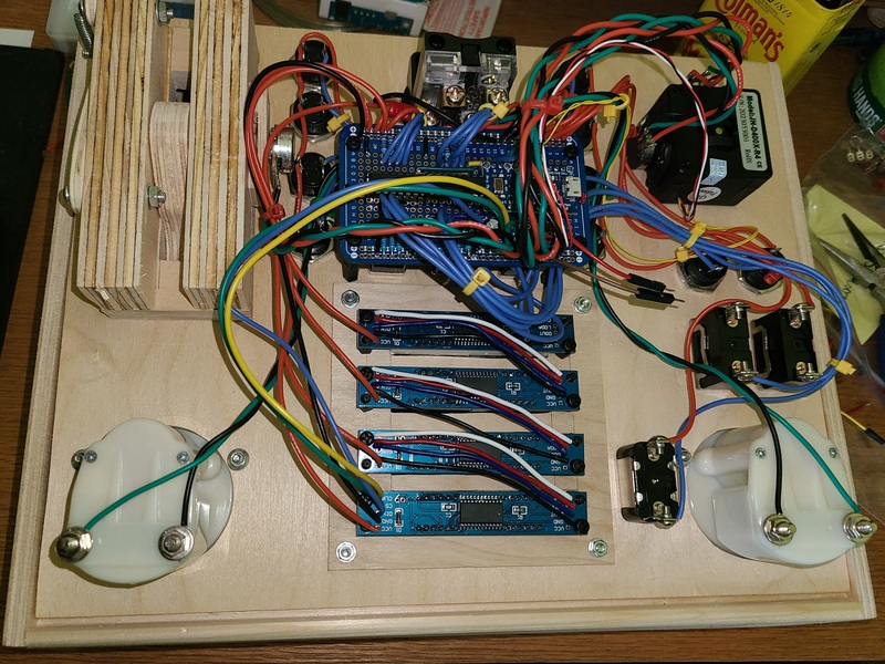
Took me a bit to think understand what is going on here. GND is likely hard because the board may have extra copper plane around the ground to handle the heavy return current. It likely has more thermal mass. Physics. You want to sink away electrons at that point as to not create transient potentials…and this has the side effect of not letting heat build up there either. You need more heat flux on your iron. Either your tip has poor conductivity or your iron cannot dump heat in fast enough. Likely the tools not the work man. More powerful soldering iron needed. The LED board designer has given you a highly conductive ground which you have now connected to a high impedance daisy chained connection…which brings us to this.

So the noise on LEDs comes from exactly this. The surges in power tow your power down. The same power you are using to reference your precision analog voltages you divide to make your potentiometer voltages that you are sampling. They will also make your grounds bounce up and down as the electrons try to find the drain and make the ground level temporarily rise. Ground bounce. It’s like dumping buckets of water into your bathtub all at once and expecting it all to instantly go down the drain without making the water level rise near the drain. If you make your voltage = 0 datum for your measurement the drain lip everything will bounce up and down as you dump electrons down the little drain (by flashing LED lights). As you say what needs to be done is you need to provide lower impedance path as parallel to your Arduino for power and ground. A proper measurement system will have several ground and power networks that all eventually meet back at the power supply.

On a precision system you will likely need capacitive bypassing like you put in as well as inductive choking on your input power to your LEDs. This will isolate the power surges from the analog power going to your measurement system. Do a search on a pi filter for power conditioning. It’s just a few inductors and caps to kill transients.

A lot of the stuff you’re seeing is the result of the Maxim LED controller. Equal brightness is likely current balancing done on the controller. Less hardware issues are because wiring complexity is encapsulated inside the Maxim chip not on your breadboard. Noise because the Maxim chip really needs its own low impedance power and ground network. Read its data sheet, it’ll likely tell you how to provide power for it in a measurement system. Daisy chaining is easy and good for data but not good for power and ground. Use a star power/ground topology instead of daisy chains.

Not sure why you remove the reverse polarity diodes. Those are to keep you from blowing up your stuff which you will eventually do if you’re using flying leads. I’d only leave that diode out if the module was permanently soldered to a board. The minute you introduce plugs and cables somebody (you) will inevitably reverse polarity. It will just take one time and you’ll be back on aliexpress or you’ll be learning SMT soldering. I get it, nobody wants to lose 0.7v forward bias to the diode and get dimmer LEDs. The designer put it there to protect you.

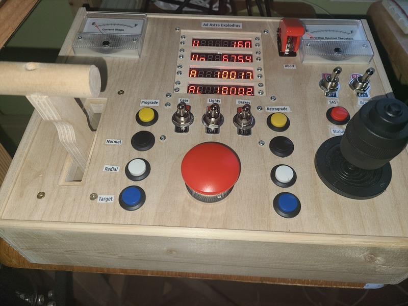
The red acetate looks really good. Look at all pro systems. They have a red window. I designed a few red led displays early in my career. The red window really increases the contrast by preventing the white unlit dies from showing through. It blacks out the black backgrounds. The notch filter of the red window must be close to the LED wavelength. When it all comes together you get that 1970s eye popping look of seven segments. Six million dollar man stuff. My favorite way to DIY this is with color laser printed transparencies. (Pre power point pre Keynote). You can print nice rectangular windows and digitally blend red/purple/orange to get that perfect pass through filter. I think an inkjet would make good ones. Don’t forget to mirror the prints because you want the ink on the inside. I’ll try to dig up an example in my junk box. It was amazing what you could do with a color laserjet loaded with transparency and Illustrator.

ETA you can also find discarded trans red gift wrap or floral wrap

jacob
Site Admin
Posts: 16001
Joined: Fri Jun 28, 2013 8:38 pm
Location: USA, Zone 5b, Koppen Dfa, Elev. 620ft, Walkscore 77
Contact:

Re: DIY Single axis USB controller

Post by jacob »

jacob wrote:
Wed Jul 05, 2023 11:24 am
[...] I'm going back to "The Mun" (Kerbal Space Program). This time I want to go in style, so I'm building an old school NASA launch board. This should be easier in terms of wood-design, because it will basically require nothing but a box, but more interesting in terms of wiring up and programming various inputs and outputs. Unlike the stick, the focus is on different buttons (safety, launch, abort, reaction control systems, ...) as well as output types (altitude, fuel, oxygen, ... ) like analog gauges and 7 segment leds. This will be on the learning curve towards a more modern (jet) simpit.
Mission Accomplished!

Here is the result:
  • 10 buttons + 5 toggle switches & a 2-stage arming switch controlled by two 74HC165s (about $20)
  • 2 pulse-width modulated analog voltmeters (I made new scales) that work as fuel gauges ($10)
  • 4 7-segment Max7219 displays that show various flight telemetry ($13)
  • 3-axis stick (these 3-axis sticks are $25 each)
  • 1 DIY throttle (50 cents)
It's fairly standard taking advantage of much of what the Kerbal Simpit library offers in terms of connectivity.
Image
Displays show: Fuel stage almost empty, vertical velocity = 16.0m/s, orbital velocity=675.4m/s, apoapsis (highest point of trajectory)=10,017m, and altitude = 10,002m. (The rocket is empty and going mostly horizontal very near the top of a suborbital parabola.)

Here's the candy on the inside:
Of particular interest might be the spring loaded throttle that provides enough friction to set it and leave it in place. Homemade design :-P

I hope I didn't do too bad a job on the cable management. Lots of considerations went into it. After each segment was wired in, it made more sense. I followed the advice about cutting everything to length. It is still made with enough length so the PCB can be flipped up (towards the black/clear/bronze screw staging button). All soldering happens on the underside. I briefly thought about wiring in from below, but that would have been a mess. My quadhand proved to be invaluable. Longer arms would have been nice.
Image

Rather than perfboard, I decided to use a stripboard with the same outlay as a breadboard. This had the advantage of being able to do unit tests of each of the entries above on a separate arduino on a breadboard before hardwiring them in. I highly recommend this technique. It makes coding so much easier as one can just more or less copy and paste the unit tests over using the same pins w/o worrying about short circuits or something not working. Incidentally, the programming side has ~500 lines of code, which uses up 52% of the memory. Note that I switched to Arduino Pro Micro ($8) which makes me feel almost professional.

In terms of soldering, you can just call me Steady-Eddie now. Micromotor control has vastly improved compared to my initial whining above, even when heavily caffeinated. No accidental bridges were committed. I checked all solder joints with a 4x watch loupe, since I no longer have the eyesight to see it "naked". I find this kind of inspection before powering up to be very good practice. It almost guarantees that the circuit is not DOA.

The worst bug was the staging button (the big red one). Somehow it only worked intermittently. I spent a day cursing figuring it was a logic problem with the debounce software routine. I tried three different ways of coding it. Testing continuity with a meter showed no problems?!?! I rebuilt/reprogrammed the unit tests (it's just a button) but they didn't work either. I experienced a period of dread figuring I might have burned a pin (there's no undoing this!... so 4 days of work lost) turned out to be me creating software bugs in the new testing routine. Stupid noob stuff like: if (button = HIGH) digitalWrite(LEDpin,HIGH) ... Fixing that, the staging button still didn't work. As a last act of desperation, I wired in a second button. This magically worked, so obviously the problem was in the big red button itself. However, it could be wired both in a momentary-on and a momentary-off configuration. Turns out that the button worked when it was upside down but not right-side up! And this is why a single button on an actual aircraft costs $50+ instead of this plastic POS component. Solution: I rewired it to momentary-off and flipped the logic. Now it works no problem.

Labels are paper and packaging tape on dusty plywood. Doesn't work that well but better than nothing.

Cost: If all components are added together, we're looking at about $65 in material. I spent about 3 times as much due to "buy 10, use 3". As a hobby, it's not free, but not too expensive either. Once I get tired of going to space, I'll try to sell it to some wannabe astronaut.

Conclusion: Finishing this was quite the confidence booster in terms of building future "mechatronic" gadgets.

PS: The odd-shaped lever for the throttle is upcycling some scrap wood from a DIY clock I made. I like to put some personal project history into each new project.

User avatar
Sclass
Posts: 2809
Joined: Tue Jul 10, 2012 5:15 pm
Location: Orange County, CA

Re: DIY Single axis USB controller

Post by Sclass »

Looking good. Nice clean build.

delay
Posts: 209
Joined: Fri Dec 16, 2022 9:21 am
Location: Netherlands, EU

Re: DIY Single axis USB controller

Post by delay »

jacob wrote:
Sun Nov 26, 2023 5:26 pm
Mission Accomplished!
Congratulations and pleasant journey to The Mun!
jacob wrote:
Sun Nov 26, 2023 5:26 pm
turned out to be me creating software bugs in the new testing routine.
The famous Heisenbug: a bug that disappears or alters its behaviour when one attempts to probe or isolate it. Real software engineering fun. Kind of amazing that they appear in what must be relatively simple programs.

J_
Posts: 892
Joined: Tue Nov 01, 2011 4:12 pm
Location: Netherlands/Austria

Re: DIY Single axis USB controller

Post by J_ »

@jacob: what an improvement of your technical skills. I remember your first diy rake! Congratulations.

AlpineTR
Posts: 21
Joined: Wed Mar 22, 2023 7:53 pm

Re: DIY Single axis USB controller

Post by AlpineTR »

This is such a cool thread. It makes me want to start playing with flight sims again.

By the way, @jacob, I was wondering how Rise of Flight was available for free (albeit with in-game purchases) and I noticed that it’s made by a software developer out of Cyprus with help of the Russian government (i.e., the Russian Military Historical Society).

jacob
Site Admin
Posts: 16001
Joined: Fri Jun 28, 2013 8:38 pm
Location: USA, Zone 5b, Koppen Dfa, Elev. 620ft, Walkscore 77
Contact:

Re: DIY Single axis USB controller

Post by jacob »

AlpineTR wrote:
Tue Nov 28, 2023 12:20 pm
By the way, @jacob, I was wondering how Rise of Flight was available for free (albeit with in-game purchases) and I noticed that it’s made by a software developer out of Cyprus with help of the Russian government (i.e., the Russian Military Historical Society).
DCS (started in Russia, now in Switzerland) is also free, but each plane and each scenario come as $$$ DLCs. This seems to be the current business model. Either give the game away or sell it at a low price. Once the player is captured/locked-in, they make the money by selling the planes individually. FSX and FS follow the same business model. It actually makes sense since once the physics-model has been programmed, all that remains to add yet another plane is to program and make the cockpit for yet another plane. I know that some of the serious flightsim youtubers have spent thousands in order to have all the planes. I think this business model is also linked to how sims no longer come with a campaign component. They practically depend on an online scene of multiplayers. As such, the game itself is more like the entry ticket, but the money is made by selling new planes, tanks, ships, etc. as gamers get bored with the old ones. This way, gamers get locked-into the platform.

I do get the impression that flight sims (both players, developers, and hardware producers) are more popular in Europe and China. It seems like it never really caught on here again in the US after the "flightsim-winter" of the 2000s.

Fun fact: Kerbal Space Program was made in Mexico.

PS: The 4x games from Paradox (Sweden) have been discussed here and there on the forum as well. Same business model. The game is cheap (say $10-20) but if you want all the DLCs, you can easily spend $150-300 which is crazy. Yet spread over a few years it doesn't seem so bad. That's how they get you :mrgreen:

User avatar
Sclass
Posts: 2809
Joined: Tue Jul 10, 2012 5:15 pm
Location: Orange County, CA

Re: DIY Single axis USB controller

Post by Sclass »

J_ wrote:
Tue Nov 28, 2023 6:07 am
@jacob: what an improvement of your technical skills. I remember your first diy rake! Congratulations.
For some reason this got burned into my memory. :lol:

jacob
Site Admin
Posts: 16001
Joined: Fri Jun 28, 2013 8:38 pm
Location: USA, Zone 5b, Koppen Dfa, Elev. 620ft, Walkscore 77
Contact:

Re: DIY Single axis USB controller

Post by jacob »

This looks like a quicker and easier way to integrate a DIY controller with a sim. It avoids having to manually program the Arduino, which may be a good thing or a bad thing depending on one's perspective. Personally, I prefer to do my own programming because it avoids black boxes and relying on other people's software.

https://www.youtube.com/watch?v=a706b1QiUp8 + https://www.mobiflight.com/en/index.html

In the video, everything is wired up with DuPont connectors, so no soldering required but also more risk of noise on the Max7219 displays. In any case, it's possible to build this in a shoebox after ordering a few buttons from amazon.

User avatar
Slevin
Posts: 648
Joined: Tue Sep 01, 2015 7:44 pm
Location: Sonoma County

Re: DIY Single axis USB controller

Post by Slevin »

jacob wrote:
Sun Jan 21, 2024 10:18 am
Personally, I prefer to do my own programming because it avoids black boxes and relying on other people's software.
It’s open source software. You can read it, decide whether it works for you, and even fix bugs if you come across them. If you have a small open source library on GitHub, it’s really wonderful for another random human to come along and start using it, and start contributing (provided they follow style guides / standards / etc). There is a lot of value in not building the same wheel an infinite number of times.

A great thing to do when you come across another library doing the same thing as one you built is to see if they have implemented features you didn’t consider but would want or edge cases you didn’t think about, and use it to upgrade your own library.

In the field of software dev (and life), you rarely get to start from zero, and the things you build will generally (hopefully) live on much past your tenure. Thus, a good engineer designs for future people and maintainance, and an important skill is being able to contribute to work other people have created (takes much more skill than a green field project).

jacob
Site Admin
Posts: 16001
Joined: Fri Jun 28, 2013 8:38 pm
Location: USA, Zone 5b, Koppen Dfa, Elev. 620ft, Walkscore 77
Contact:

Re: DIY Single axis USB controller

Post by jacob »

@Slevin - Good point! I'm historically conditioned to "remaking tools from scratch" (in order to explore possibly undiscovered science/not trusting existing tools to be good enough) but for something like this, it makes more sense to figure out how to optimize together.

Post Reply