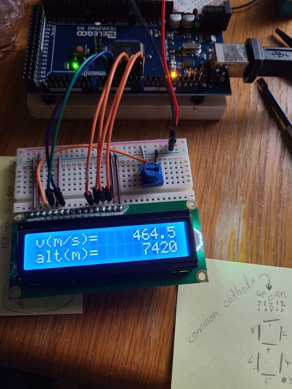
Some of my early outputs looked a lot like Predator's wrist computer
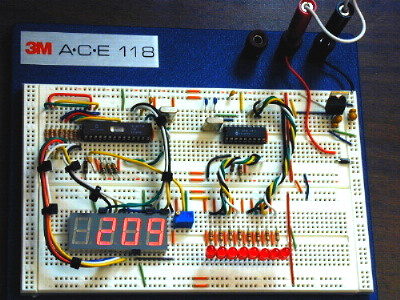
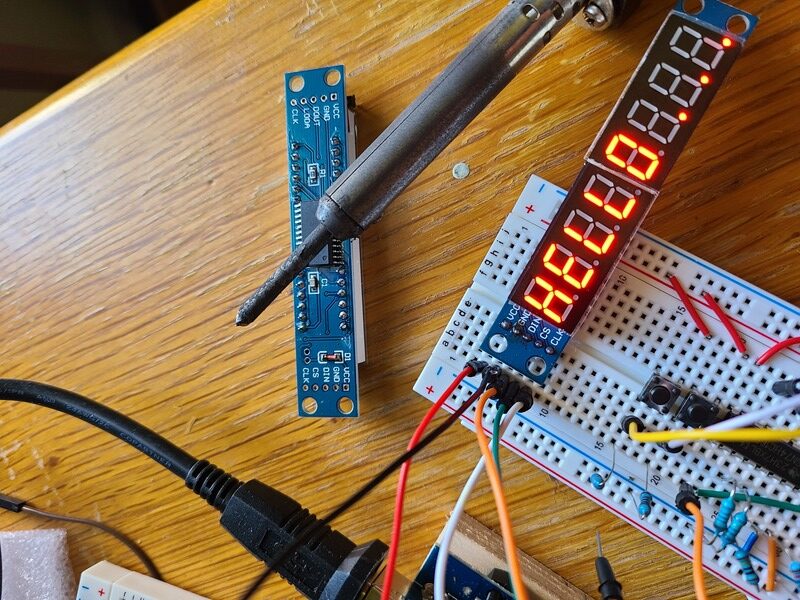
What I have is a size=10 byte array called digits where each array entry shows what segments to light up. E.g. digits[2] = B11011010 and a size 4 byte array called position to pick which of the four common cathodes to sink into, e.g. position[3] = B11111011. Then I just feed a set of those into the two shift-registers to light up one number. E.g. if I want to light up the hundreds, I'll SIP feed position[3] followed by digits[(int)(velocity/100)%10)] bit-by-bit while flipping the clock pin back and forth. This sounds like what you had?
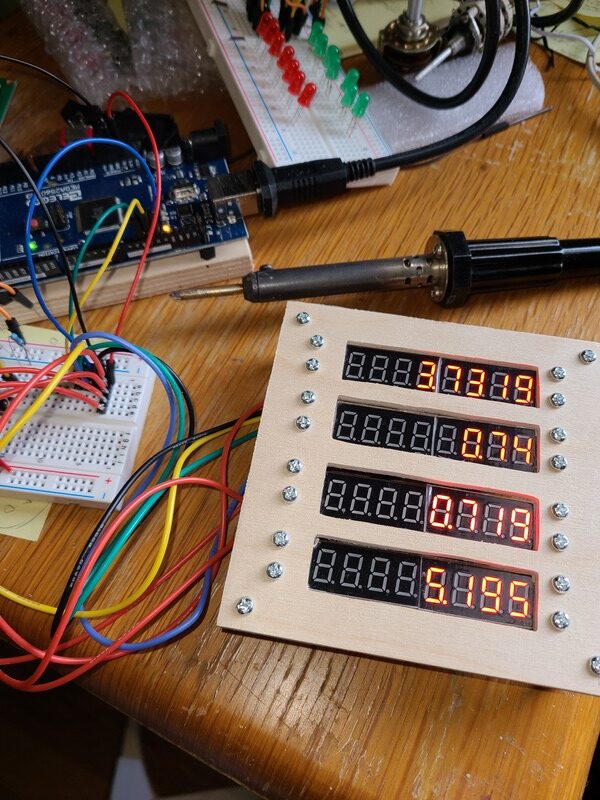
I do worry whether the Arduino will be able to keep the digits lit "enough" once I start adding more displays to the loop() cycle. (I have noticed that "small" digits like 1 are brighter than "large" digits like 8. Fortunately, my marketing department was the first to volunteer for my astronaut corps. They were as brave as the rest but rather more stupid
I prefer the 1960s Starship Enterprise style and programming from scratch for KSP. Early on I used a library, but I wasn't happy not knowing what was going on under the hood. (The stitch'n'glue approach to programming just doesn't appeal to me.)
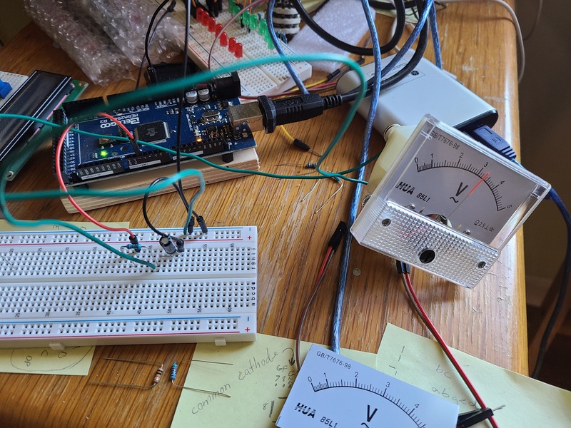
I'm thinking of getting some 5V voltmeters to use as fuel-gauges using pulse width modulation, e.g. outputting 4V on the pin would show 80% full. Just have to find some cheap ones. 5V seems rare, but 5V is what the Arduino offers. Any ideas?
I've seen a couple of OLED displays in people's KSP controllers(*), but that will have to wait for the multifunction displays for the next project, e.g. Cessna172, A10, F16, or Boeing737. Who am I kidding, it'll be the A10
(*) One potential style-cheat worthy of an OLED would be the Nav-Ball (as seen in the center bottom for the video I included above).
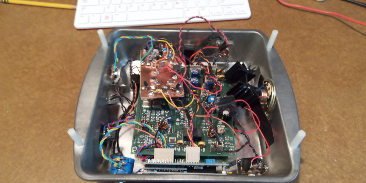
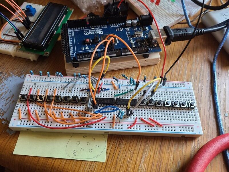
I did look into button matrices. The amount of wiring required is brutal though, especially given my rat's nest wiring style. I really need to figure out how to prettify my wiring. One problem with the shoebox approach is that everything is best kept on the lid lest one uses really long wires. I don't have a good solution yet. It's a mess. It might be better to compartmentalize with a bunch of small protoboards, like the one at the bottom of the shoebox, instead of feeding a single large one.